To enhance SiC power device reliability, understanding failure mechanisms under short-circuit conditions is crucial. While SiC theoretically offers higher thermal limits due to its wider band gap, practical constraints such as higher current density and smaller chip area impose limitations on its short-circuit withstanding capability. To address this, a new safety criteria based on short-circuit current and gate voltage have been proposed, offering a practical and cost-effective approach to defining Short-Circuit Safe Operation Areas (SCSOA) for SiC devices, crucial for ensuring their reliability in diverse operating conditions.
- 中文简体
- 中文繁体
- English
- Русский
- 日本語
- 한국 사람
- Français
- Deutsch
- हिंदी
- Português
- Español
- بالعربية
- Corsu
- guarani
- kinyarwanda
- Hausa
- Norge
- Nederlands
- Yoruba
- गोंगेन हें नांव
- Latina
- नेपालीName
- čeština
- ʻŌlelo Hawaiʻi
- ჯორჯიანიName
- فارسی
- भोजपुरी
- беларускі
- Kiswahili
- ÍslandName
- ייַדיש
- tur
- Gaeilge
- ગુજરાતી
- Slovenská
- היברית
- ಕನ್ನಡ್Name
- Magyar
- தாமில்
- بالعربية
- বাংলা
- Azərbaycan
- lifiava
- IndonesiaName
- dansk
- Shona
- Bamanankan
- Lietuva
- Tiếng Việt
- Malti
- Türkmençe
- অসমীয়া
- català
- සිංගාපුර්
- Suomalainen
- Кыргыз тили
- Eʋegbe
- Hrvatski
- a n:n
- Quechua
- bosanski
- Maori
Requirements Needed in the Implementation of the Experiment
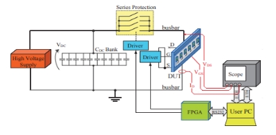
Two commercial SiC MOSFET power modules, Cree’s 1.2 kV/300 A and Rohm’s 1.2 kV/180 A, underwent a non-destructive testing (NDT) investigation at Aalborg University, Denmark. As shown in Figure 1, the NDT setup involved a high-voltage power supply charging a capacitor bank for testing up to 10 kA and 2.4 kV without device destruction. The system included protection switches, a computer-designed busbar for current distribution, and a 100 MHz FPGA for signal control and measurement acquisition. A PC facilitated data acquisition and remote control, linked to an oscilloscope and FPGA board. Cree's recommended gate driver, CGD15HB62P, was used with desaturation protection disabled. Experiments were conducted with gate-emitter voltages of +20 V/-6 V and a 5 Ω external gate resistance, ensuring proper controllability at a case temperature of approximately 25°C.

On the other hand, for the software section, an automated tool with a user-friendly GUI in MATLAB helped in the short circuit testing, ensuring maximum consistency. Users input test parameters, including test quantity and pulse interval. The GUI then passes the conditions and initiates tests, communicating the sequence to the FPGA. A 30-second off-time permits device cooling between tests. Data checks prevent fatal errors during communication and a local echo displays parameters sent to the FPGA for user reference. Following each test, waveforms are acquired through Active-X functions from the oscilloscope, capturing test index and time-stamp data for storage. This system facilitates repetitive testing, providing a reliable method for assessing device performance while offering ease of use through its intuitive interface.
- Prev:None
- Next:Building a Smart Home System: Exploring Arduino Applications
Recommend News
-
Tel
+86-0755-83269835 -
E-mail
-
Whatsapp


